Implementing HA and Scaling Deployments
Basic Daml Deployment
The diagram below illustrates the most basic multi-party Daml deployment possible.
Each logical box in the diagram contains multiple internal components in an HA production configuration. The following sections expand on each of these logical boxes to show how they are configured for production.
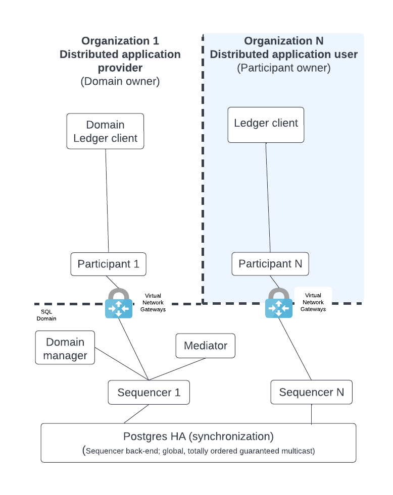
The diagram shows the following components:
- A Ledger client that uses the Ledger API; the client entry point to execute business logic.
- Participant nodes which expose the public Ledger API. They execute the Daml business logic of the distributed application based on an API request or as part of the Canton transaction consensus protocol.
- A Mediator which acts as a transaction manager for the Canton consensus protocol. Ensures that either all of the parts of a transaction succeed or there is no change.
- The Sync domain manager which manages the sync domain with transactions that update the topology and make public keys available.
- Sequencers expose the Canton API so that all clients see events as ordered by a guaranteed, multicast communication mechanism. A sequencer has a backend component that is hidden from its clients. Depending on the backend component, the solution supports either a SQL or blockchain sync domain.
Note
The term node may refer to a logical box with multiple components or a single JVM process depending on context.
The distributed application provider deploys several components: the sync domain (sync domain manager [1], mediator, and sequencer) and their own participant node(s).
The distributed application user only has to deploy a participant node and connect that node (from their own private network) to the private network of the sync domain via communication with a sequencer. [2]
A typical Daml deployment has additional components which are shown in the figure below:
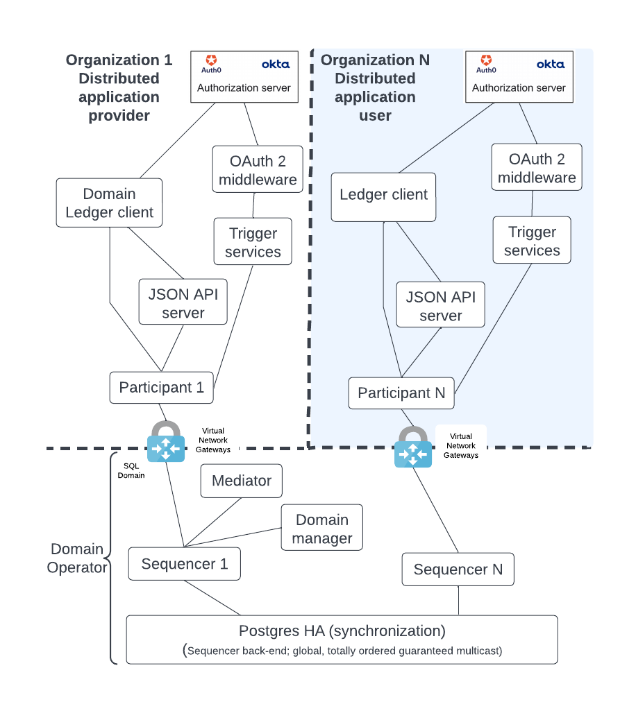
The diagram shows the following components:
- An HTTP JSON API server which supplements the gRPC API endpoints of the participant node by providing an HTTP REST (HTTP JSON API) endpoint. It also has an internal cache so that it can be more responsive to queries.
- Trigger services that listen to the ledger event stream for events that trigger business logic.
- OAuth2 middleware that supports a refresh of the Trigger services JWT token and manages the background requests for a refresh token for the Trigger services.
- The Identity Provider (IDP) is the authentication entity that provides the JWT token. The IDP is outside of the Daml solution but nevertheless a necessary component. Different organizations may use different IDPs for their participant nodes.
Note
We expect the sync domain owner to implement additional business logic for managing the distributed application in both their participant node and trigger service nodes.
Architecture for HA and Scaling
As a production system becomes busier, it is necessary to scale up the components.
Vertical scaling is the easiest way to handle more load, but there are limits to its benefits. Vertical scaling is not discussed here since this is a well-known technique. Instead, this document focuses on horizontal scaling where backup/redundant components are deployed to different availability zones as part of the HA configuration.
Note
For clarity the diagrams follow these conventions:
- Solid, black boxes for individual instances, processes, and containers.
- Databases may be identified as shared and highly available with an HA in the disk figure.
- Distinguishing between a single instance and the HA variant is done by using the term service for HA. There is also a blue dashed line around the components that make up an HA service. The word service is chosen because it looks like a single endpoint which is highly available, like a managed service in the cloud.
- For simplicity, a blue dashed box with a name is shorthand for the HA variant of that component.
- Health signals are a dashed red line that point to the instance that is a recipient of that signal.
- Communication channels that are passive but become active upon failover are bordered by a dashed green line.
Thus, in the figure below, the Middle service blue box encompasses all the components that make up that service. Middle services instances are in black boxes with solid lines. The blue box Another is short form for a service called Another. There is a load balancer between the middle and bottom services.
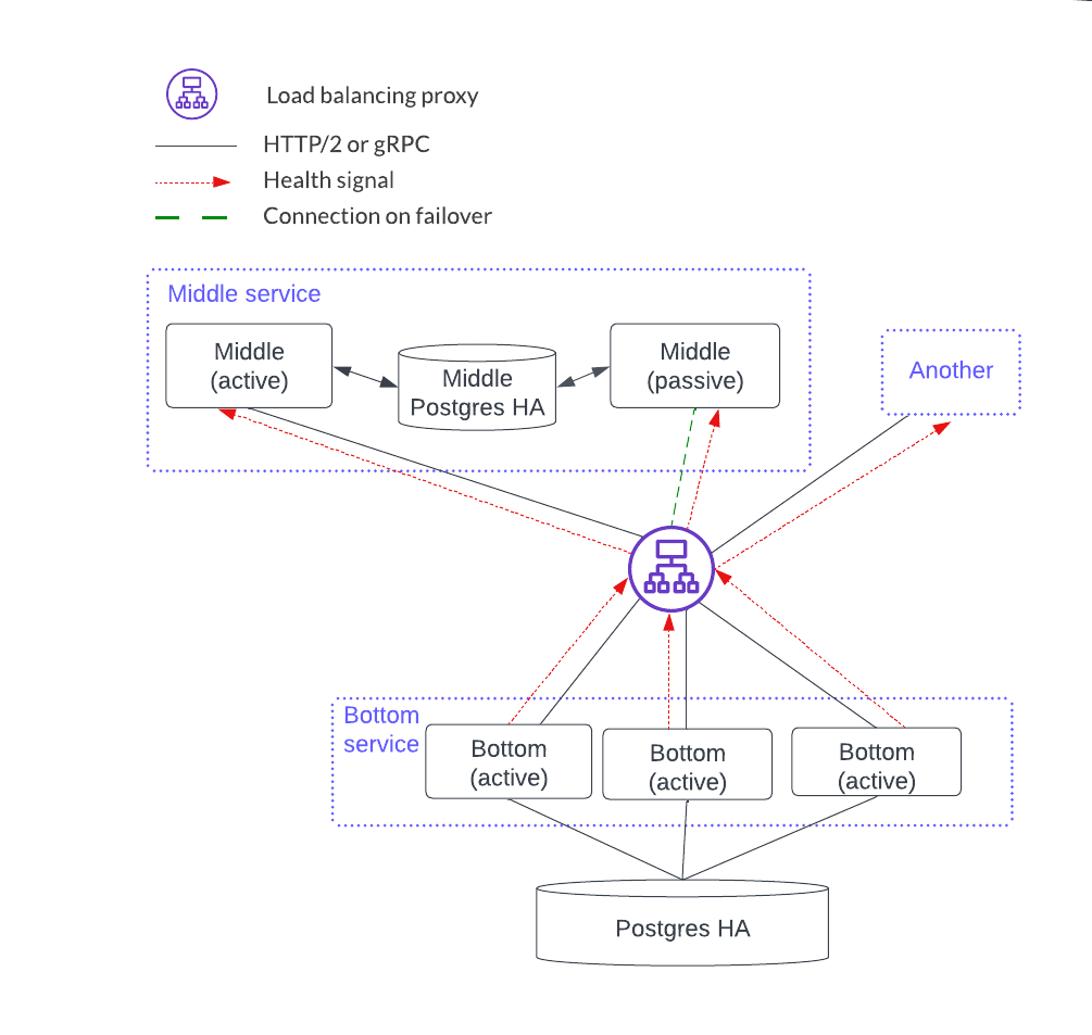
Each component can scale using a stateless or stateful horizontal scaling pattern. In this diagram, the bottom service has instances that are independent and considered stateless. Stateless horizontal scaling is achieved by adding another bottom instance. This also increases the availability because there are more redundant instances. The middle service is stateful since the instances share a local database so the HA model is active-passive. Scaling the stateful middle service is achieved by replicating the entire middle service: i.e. add two instances connected by a PostgreSQL HA database.
HTTP JSON API and Participant Node Services
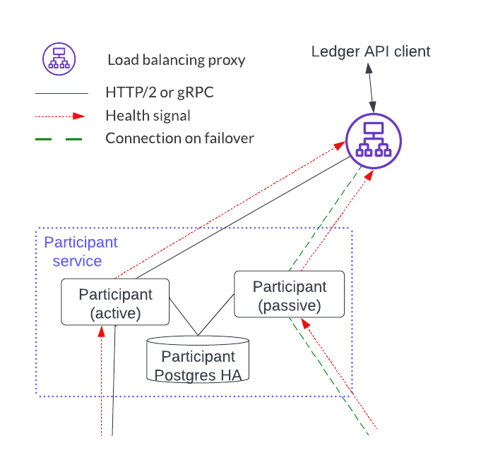
In cases where there is a single participant service (and corresponding HTTP JSON API service) that all the client requests go to, the HTTP JSON API and participant services need to be considered together since there are some state dependencies between the two. In particular, users and related parties are configured on a participant node so they will be handled by a particular participant service. This means that the HTTP JSON API service that is connected to a participant service also serves those same users and parties.
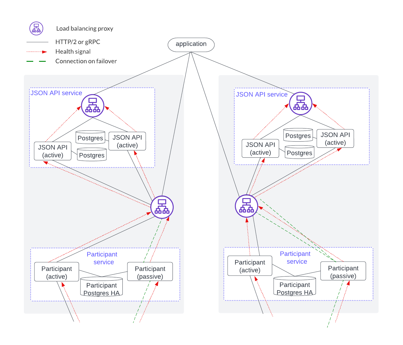
However, if there is more than one participant service (e.g. with horizontal scaling) then it is the application’s responsibility to understand which participant service to send a request to (and the corresponding HTTP JSON API service), based on the user(s) or parties of the request. Another way to describe this is that users and parties are sharded across the participant and HTTP JSON API services and the application is responsible for targeting the right instance.
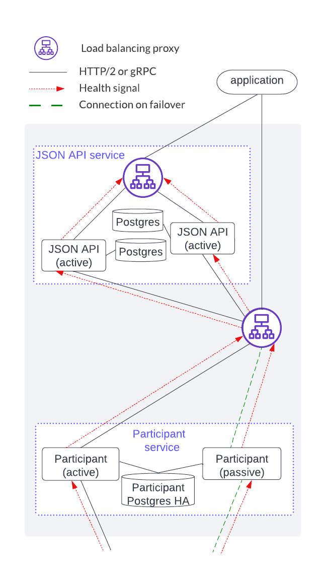
As shown below, an HTTP JSON API service is an endpoint that has four components. Each HTTP JSON API instance emits a health signal that the load balancer uses to direct traffic. The HTTP JSON API’s database acts as a cache that is local to the instance, meaning it does not need to be HA since the cache can be reconstructed at any time.
Note
The HTTP JSON API server does not currently support mTLS from client applications. mTLS is supported between the load balancer and participant node.
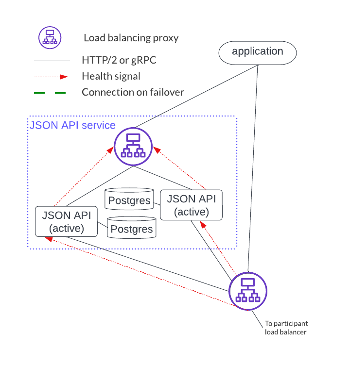
There are a couple of important distinctions between the participant service and the HTTP JSON API service setup:
- A single participant service can have several HTTP JSON API servers. However, a given HTTP JSON API server should only connect to a single participant service.
- The HTTP JSON API component operates in an active-active mode while participant nodes operate in an active-passive mode.
The deployment below shows a single HTTP JSON API service and participant service. There are some hidden state dependencies that include:
- A ledger offset that requires the HTTP JSON API server to be associated with a single participant service.
- Command deduplication functions on a single participant service alone.
- Shared users and parties for both the HTTP JSON API service and the participant service.
Horizontal scaling is accomplished by sharding application users and parties across a joint HTTP JSON API and participant service, and adding another HTTP JSON API and participant stack, as shown below.
Sequencer Service
The sequencer service operates in active-active mode, which means that all sequencer instances can accept and process Canton protocol API requests. This has benefits for both scaling and availability.
Deploying a sequencer depends on business requirements which may impact deployment configurations such as load balancing configurations and whether the sync domain is fully or only partially decentralized.
Sequencer service load balancing options
The sequencer service has several clients: participant, mediator, and sync domain manager. mTLS between these clients is unavailable at the time of writing.
The two available load-balancing options are shown in the diagram below.
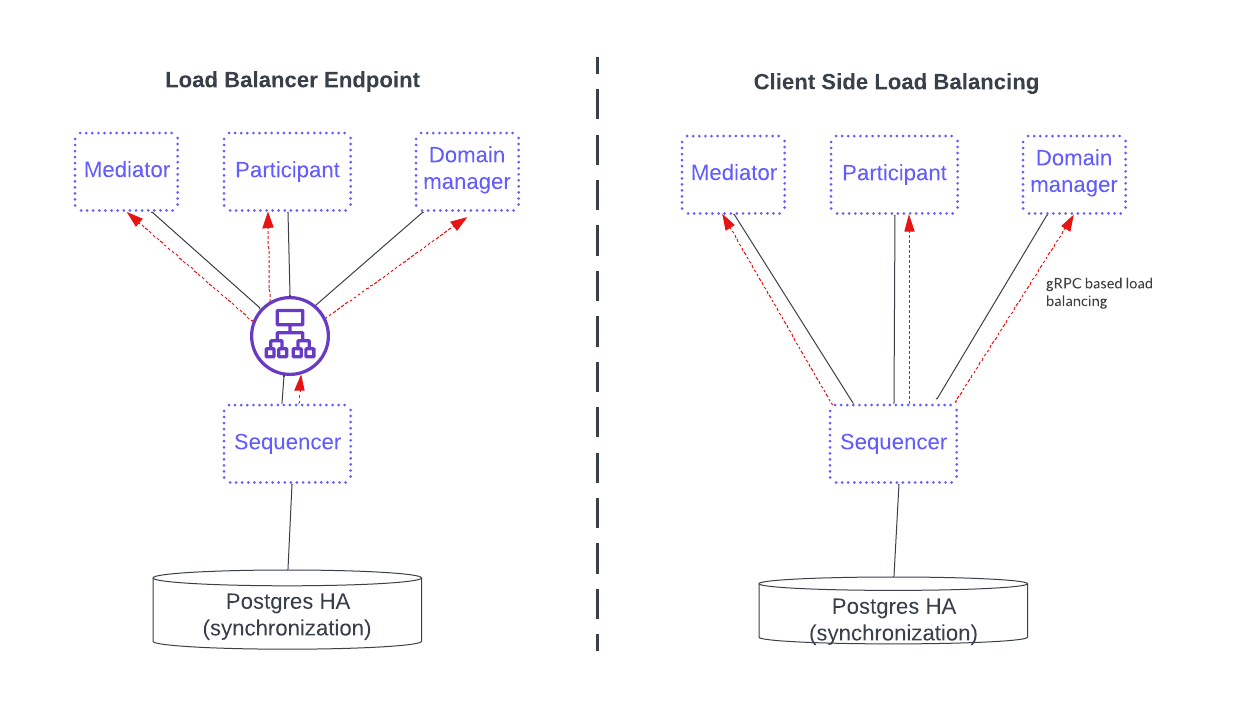
The first option, on the left, fronts the sequencer service with a load balancer that all sequencer clients use. This option simplifies configuration and connectivity but adds the complexity of configuring the load balancer.
The option on the right is a gRPC java client library providing a round-robin selection mechanism for load balancing that automatically round-robins through multiple sequencer connections and includes the healthy ones. This setup requires the distributed application provider and distributed application users to maintain the configuration information of all the available sequencers in the sequencer client. The sequencer client continuously monitors the health of each sequencer endpoint when selecting a possible node in a round-robin fashion.
See the Canton documentation on connection to high availability sequencers and client load balancing for more information.
Blockchain synchronization domains
A blockchain sync domain has a fully decentralized data path and is used when there is no trust between the distributed application providers and users. Whereas the sequencer queries the PostgreSQL backend directly in a SQL sync domain, this cannot be done in a blockchain sync domain. Instead, a local database to the sequencer is added to speed things up. The sequencer backend then uses the blockchain to provide a guaranteed ordered multicast of events.
The figure below shows a HyperLedger Fabric blockchain example. Notice that each sequencer has an independent local cache running on a PostgreSQL database. This local cache ensures efficiency because the sequencer avoids having to scan the entire blockchain when it starts up or reconnects after a temporary interruption. It also reduces the performance load on the blockchain.
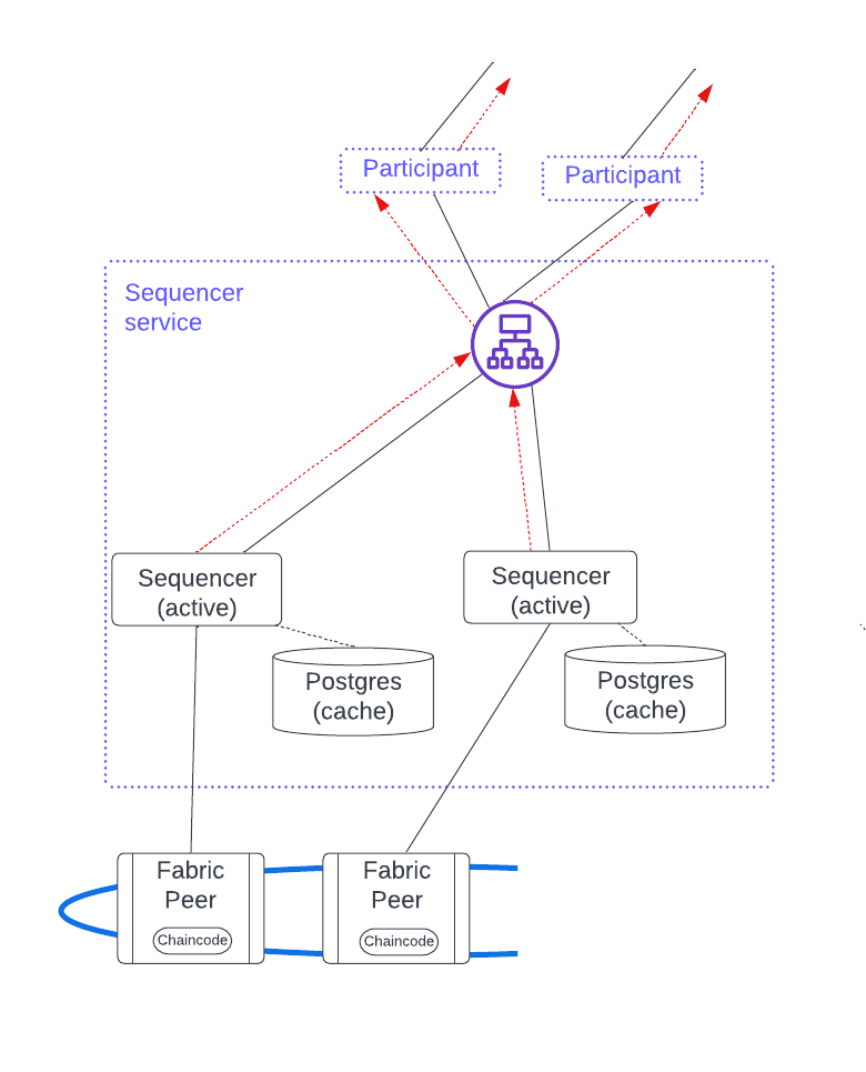
This figure has a load balancer fronting the sequencer nodes, but client-side load balancing would also work. There are several benefits to using a load balancer:
- Clients have a single endpoint that consolidates the health signals, simplifying setup and troubleshooting.
- Adding a sequencer does not require updating the configuration information in each client.
- Additional security.
Since sequencer nodes are always active, horizontal scaling for a blockchain sequencer service is achieved by adding a new sequencer along with its associated local cache database and enabling it for client use.
SQL synchronization domains
The SQL sync domain is only partially decentralized and is used when the sequencer’s backend data is stored in a single PostgreSQL database managed by a centralized distributed application provider. This option requires participant users to have some trust in the application provider.
A sequencer needs no local cache because it queries the backend database directly with no performance penalty.
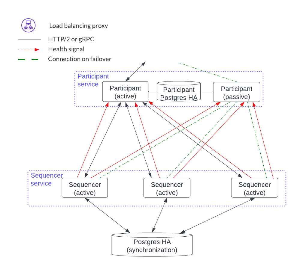
Since sequencer nodes are always active, horizontal scaling for the SQL sync domain sequencer service is achieved by adding a new sequencer and enabling the clients to use it.
Mediator Service
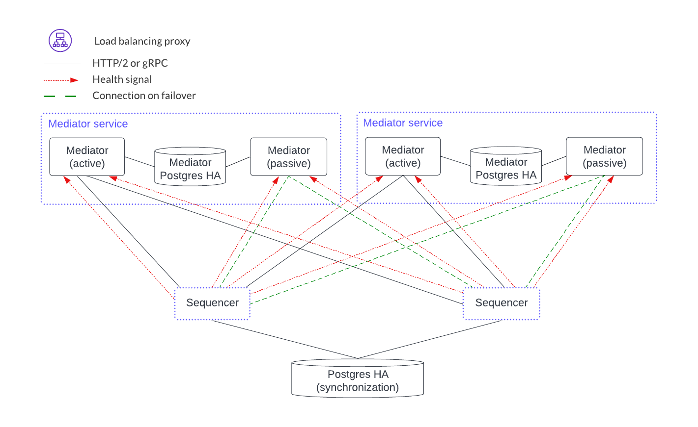
The mediator service has no client-facing ingest. It also has no load-balancing proxy or health endpoints. Instead, it uses client-side load balancing based on the gRPC infrastructure. It is like the participant node in that it has a PostgreSQL database in an HA configuration. The mediator components, however, act in an active-passive configuration.
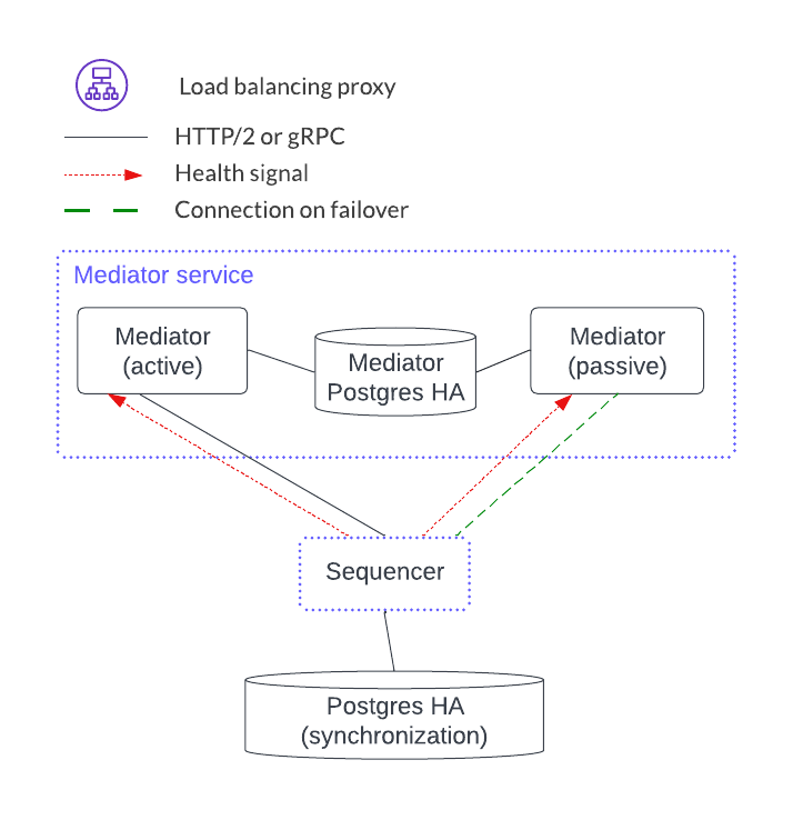
Horizontal scaling is achieved by adding another mediator service.
Synchronization Domain Manager Service
The sync domain manager service also has no client-facing ingest point. Like the mediator services, the sync domain manager is in an active-passive configuration. There is, however, only a single sync domain manager service per sync domain. This means that there is no horizontal load-balancing model for the sync domain manager. This is feasible because the sync domain manager is not in the transaction processing path path and so it manages topology transactions which are orders of magnitude less frequent than the Daml transactions that the mediators manage.
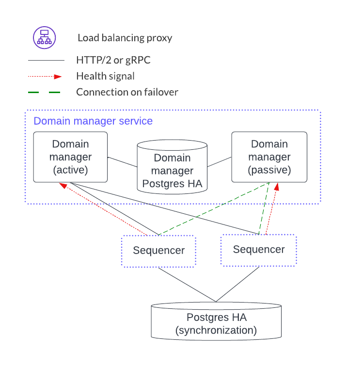
As of v2.5.0, the syncrhonizer manager uses PostgreSQL in an HA configuration for HA support.
Trigger Service
The trigger service includes the OAuth 2.0 middleware and trigger service nodes. As shown below, it does not operate in an HA configuration that supports a single failure. Instead, it requires a monitoring system to detect if the trigger service node or OAuth 2.0 middleware is unhealthy and mitigate any issues by doing one of the following:
- Restarting the failed item.
- Stopping the unhealthy instance and then starting another instance.
A shared PostgreSQL database is needed for the trigger service node. As shown below, the OAuth 2.0 middleware connects to an OAuth provider.
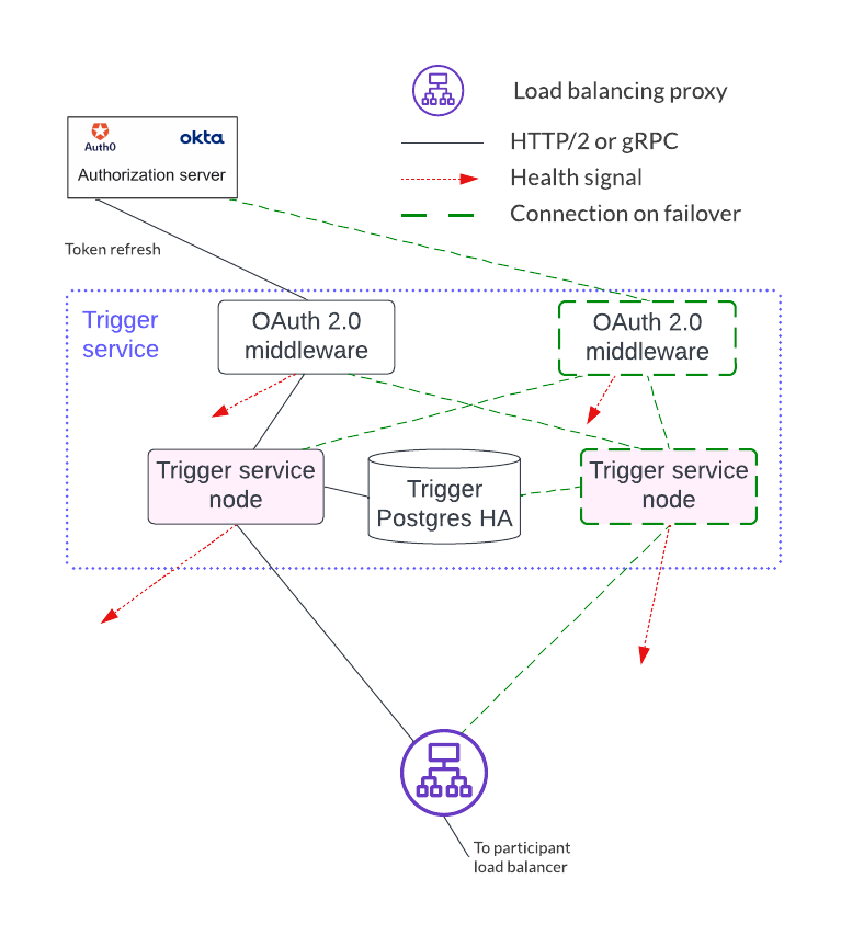
Horizontal scaling is achieved by deploying additional trigger service nodes. For example, in the figure below, there are two pairs of trigger service nodes (pink and green) which use the same OAuth 2.0 middleware node that is connected to a single OAuth provider.
Running the same trigger rule on multiple live trigger service instances is not allowed. In this example the pink rules are running in a single live trigger service node, just like the green rules are running in a single live trigger service node.
Remember, the box with the dashed lines indicates that the node is started when the active node is identified as unhealthy.
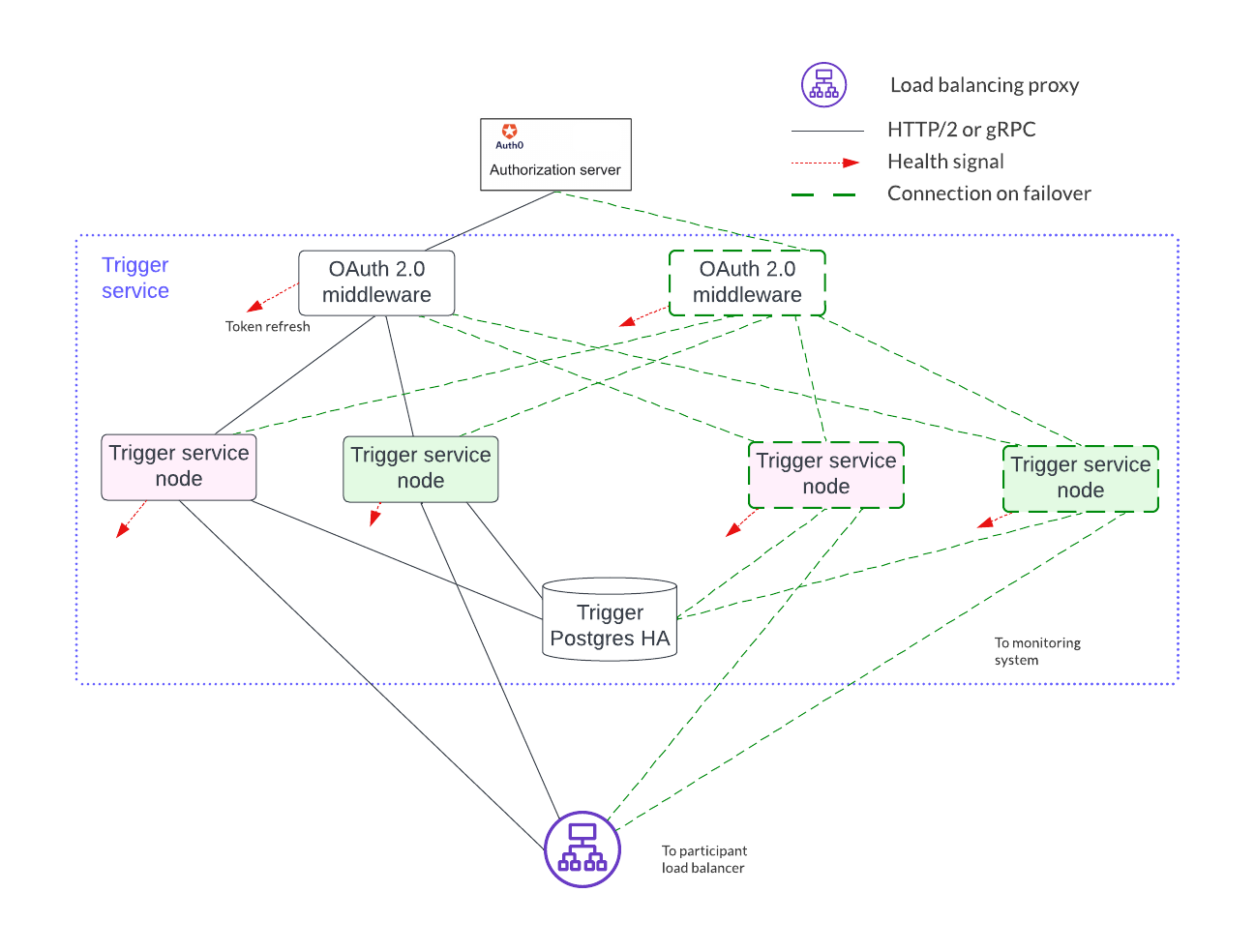
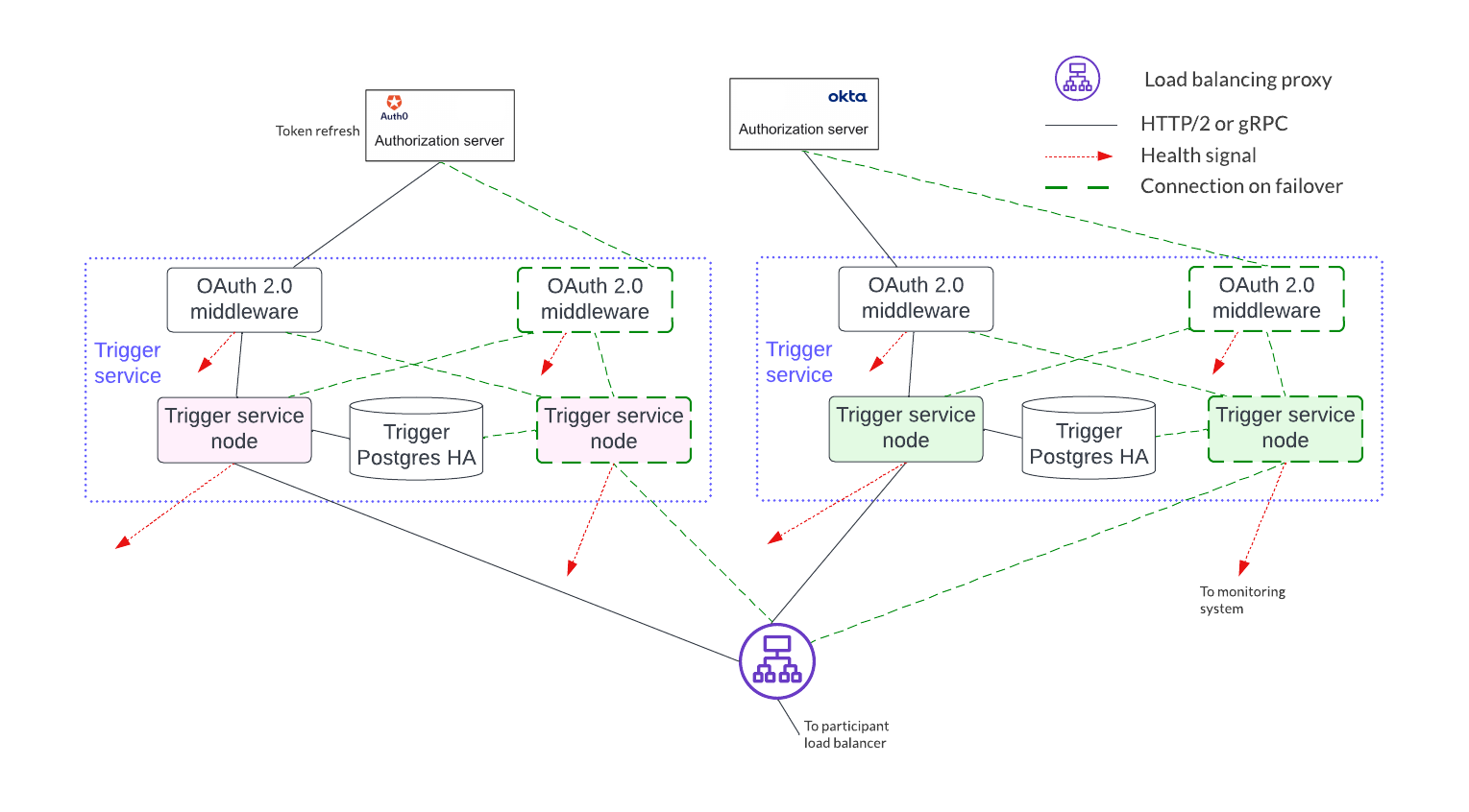
Each trigger service node is limited to a single OAuth provider and is unable to support queries against multiple OAuth providers. For example, the pink and green trigger services in the figure above cannot query against both a Google OAuth provider and an Apple OAuth provider - each trigger service must be configured to use exactly one of these providers.
If access to more than a single OAuth provider is needed, distinct pairs of trigger service nodes and OAuth 2.0 middleware servers are configured. This is shown below. Please note running the same trigger rule on multiple live trigger service instances is not allowed in this configuration either.
Footnotes
| [1] | The sync domain manager can also be referred to as the ‘topology manager’. For a production deployment, the sync domain manager can be thought of as containing the topology manager with some additional capabilities. |
| [2] | Although there are multiple sequencers shown, this is just for illustration purpose. As little as a single sequencer is needed. For example, Organization N’s participant node could connect to Sequencer 1 and not Sequencer N. |

